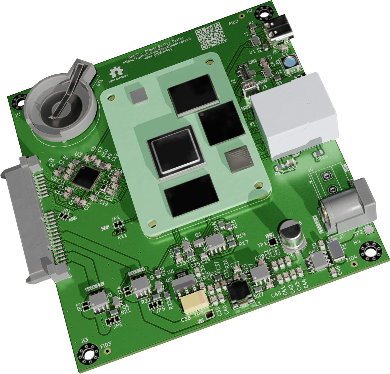
Board
3D Renders
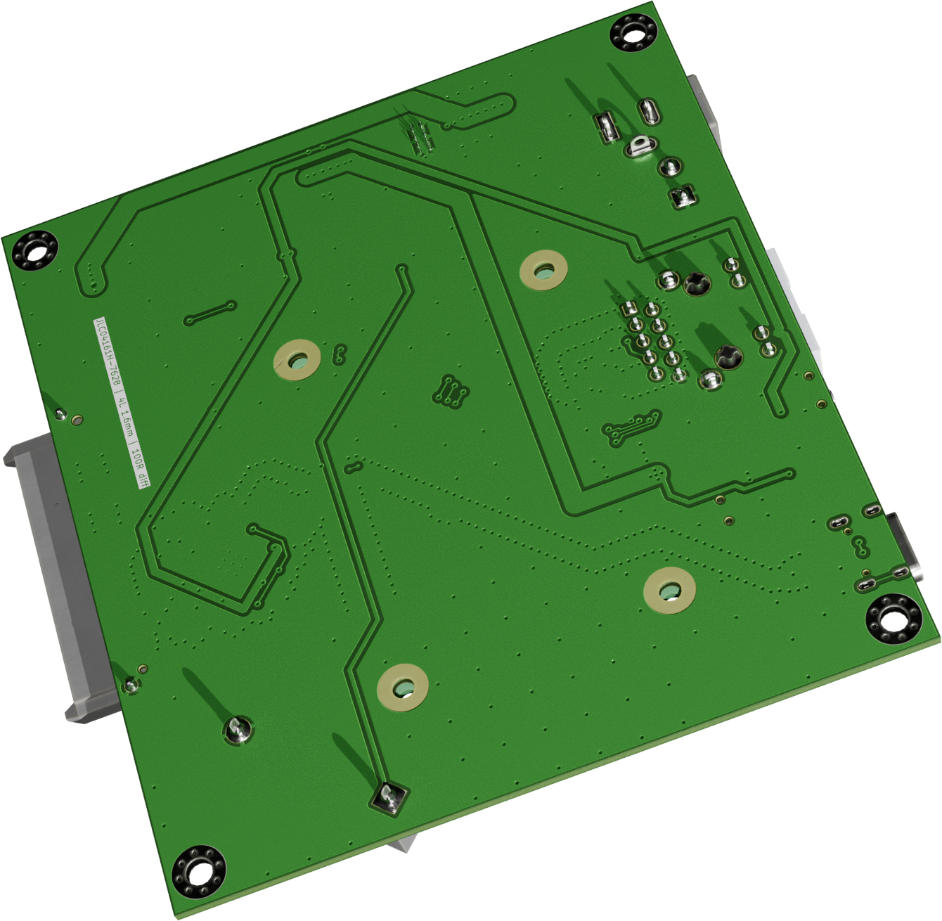
Schematic & PCB
Interactive BOM
For detailed circuit design notes, PCB routing guidelines, and netclass definitions, see hardware/docs/DESIGN.md.
Key Design Decisions
ASM1061 over USB-to-SATA bridges
Native PCIe SATA controller using the standard Linux ahci driver. No proprietary firmware blob required — the SPI flash footprint can be left unpopulated. SMART works natively without SAT translation hacks. Full SATA III throughput on both CM4 and CM5.
12V DC input
Required for 3.5" HDD support (spindle motor needs 12V). AP64501SP-13 accepts 3.8–28V. Both barrel jack and screw terminal footprints provided — populate one at assembly time.
USB-C OTG
Single USB-C connector for eMMC flashing (rpiboot) and USB mass storage gadget mode (initial backup seeding). USB 2.0 device mode only, with USBLC6-2SC6 ESD protection.
SATA power control
12V and 5V to the SATA connector are software-controlled via GPIO5. HDD is off by default at boot — powered on explicitly by software. Solder jumpers (JP5, JP6) allow changing the default without a PCB respin.
Boot and storage strategy
Full OS on CM4 eMMC (no SD card slot), SATA HDD dedicated to backup storage only. No SD card — eMMC is more reliable for a deploy-and-forget device. Backup data is encrypted client-side (e.g. by Restic or rclone crypt). Full-disk encryption via LUKS is optional.
Reuse from pedalboard-hw
CM connector, power supply (AP64501SP-13 buck + NCP1117 LDO), USB power switch (AP2553W6), KiCad symbol/footprint library.